Common Amplifier Format: Crown CTs 2000
by Pat Brown
Pat Brown continues with “Common Amplifier Format (CAF)” series. In this article, he overviews the Crown CTs 2000 amplifier, a workhorse in the commercial sound market.
Crown Audio makes a lot of amplifier models to address the many subfields in the professional audio marketplace. The CTs 2000 (now discontinued) is a workhorse in the commercial sound market. Why review a legacy amplifier? Because there are tons of these still in service, and it has some interesting behaviors that help paint a picture of how modern amplifiers perform and are rated. The unit I tested served at a major sports arena before being replaced by a newer model.
The detail test results are available in the Common Amplifier Format (CAF). You can download the freeware CAFViewer here. You can download the CAF file for this amplifier here. Please note that v1.1.2 is the latest version, and is necessary for properly viewing the CAF file.


Photo 1 – The Crown CTs 2000 (courtesy Crown website)
Rated Power
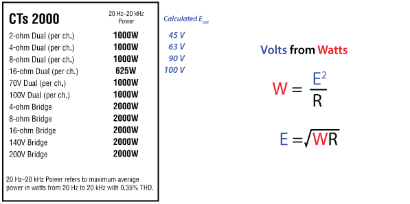
I’ll start this overview with the amplifier’s rated power as given by the manufacturer, shown in Figure 1. A first step in testing an amplifier is to determine what to expect with regard to the output voltage. The maximum power based on a harmonic distortion limit can only be measured with a sine wave since by definition any broadband signal will have a higher crest factor and therefore produce less than the sine wave power. To this end, the CAF includes a 20 Hz – 20 kHz log sine sweep, as well as single frequency 1 kHz and 50 Hz tests.

Figure 1 – Output voltage estimation as determined from rated power.
Since the rated power at 8, 4, and 2 ohms is the same (1000 watts), the voltage must drop under load. This is a very general presentation of the amplifier’s performance. The intuitive deduction is that one gets the same power, regardless of load impedance, which sounds like a good feature if your amplifier philosophy is “all that matters is power.” If you are in the “wave shape preservation” camp, these load-dependent voltage changes can be avoided by keeping the load impedance up toward 8 ohms and/or avoiding very low crest factor program. For an amplifier to preserve the shape of the voltage waveform in lieu of the frequency-dependent impedance variations found in real-world loudspeakers it must have a near zero output impedance and plenty of available current. The CTs 2000 has both if it is not excessively loaded.

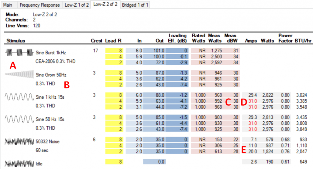
Figure 2 – The I/O Matrix for the CTs 2000, both channels driven.
A – The sine grow test was used in lieu of a 50 Hz burst test.
B – The amplifier never reached the 1% THD allowed by the CAF.
C – The measured power of 1000W (+30 dBW) agrees with the rated power for a continuous sine wave.
D – The audio power is limited by the utility power circuit. The CAF turns the amps field red if it equals or exceeds the Maximum Current Draw specification on the Main tab of the CAF report.
E – With pink noise and a 2-ohm load, the CTs 2000 needs a 20 A breaker to reach its rated output.
Power Requirements
Note that the CAF gives the current draw and BTU output for both continuous sine waves and noise. The system designer can make the decision as to which to use based on the intended application, with the noise ratings as a minimum and the sine ratings as a maximum.
Rated Sensitivity
One must apply an input voltage to get an output voltage, and the sensitivity specification states what this voltage must be. The input sensitivity switch is behind a panel and has 3 settings. Crown labels these as per the application rather than giving the actual voltage (8/4 ohm, 26 dB, 70/100 V). I chose to use the “26 dB” setting (the lowest sensitivity choice) and the IO Matrix tabs show the required input voltage to reach the full output voltage for each load condition. For the amplifier to be able to handle the rated maximum input voltage of +20 dBu, the input attenuator must be reduced from “full up” (CAF Main tab).
The Burst Test
The CTs 2000 was not able to pass this test at 50 Hz, as the distortion was higher than the 1% allowed by the CAF. The 200 ms wavelet (which is 10x longer than the 20 ms wavelet used at 1 kHz) is distorted at any drive level. This is not uncommon, and it is one reason why 50 Hz power ratings are seldom published. When this happens I use the “sine grow” test as a fallback to find the amplifier’s rails. It’s an automated AP test that grows the input voltage until the target distortion is reached (Figure 3).
 Figure 3 – A “Sine Grow” test was used in lieu of a Sine Burst test at 50 Hz.
Some Observations
The CEA-2006 burst test is slightly higher than the continuous sine wave tests. The Keele Tone Burst tests show that the voltage of a short wavelet approaches 140 Vpeak. As such, the CTs 2000 has some dynamic headroom above its rated power. The sound system designer can decide which test type best describes their application, and then double-click on the output voltage in the I/O Matrix to load the value into the Low-Z calculator and supply the additional variables needed to make SPL and wire gauge estimates.

Leave a Reply
Want to join the discussion?Feel free to contribute!