
Common Amplifier Format: Ashly SRA-4150
by Pat Brown
Much can be learned about amplifiers by reviewing/comparing a common set of specifications that were collected in the same manner. In this series, I’ll use the Common Amplifier Format (CAF) to periodically overview a selected make and model.
Much can be learned about amplifiers by reviewing/comparing a common set of specifications that were collected in the same manner. In this series I’ll use the Common Amplifier Format (CAF) to periodically overview a selected make and model. It is the intent that these studies will benefit those taking SynAudCon training programs.
The Common Amplifier Format (CAF) report for this amplifier can be downloaded from here. Those interested can investigate the amplifier using the freeware viewer.
Disclaimer: This third-party testing was performed on a unit purchased from the normal distribution channels. It is not intended to supplant, replace, or challenge the manufacturer’s published data. Anyone deploying this amplifier should consult the manufacturer’s literature and follow the instructions contained therein.
Overview
The Ashly SRA-4150 is a four channel amplifier designed to drive direct-connected loads of 4 ohms and higher. The 1 RU form factor and fan-less design make it suitable for small, low-noise environments such as meeting rooms, home theaters, and studios.
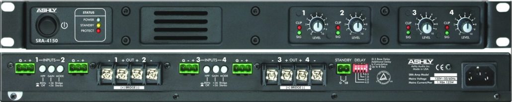
Photo 1 – Front and back panels of SRA-4150.
General Specifications
Tab 1 of the CAF gives some of the amplifier’s general specifications. Most are self-explanatory and a detailed explanation can be found on the CAF website. I will comment on a few measures specific to this unit.
The input impedance is a very high 26 kΩ and the output impedance is a very low 21 mΩ. Both values are typical for modern amplifiers. All inputs in parallel present an impedance of about 6.2 kΩ to the source. The band limits of 12 Hz and 30 kHz (-3 dB) assure a very uniform transfer function through the audible range of 20 Hz to 20 kHz.
The input stage clipping voltage of 6 VRMS (18 dBu) is high enough to accept the full-scale output of many mixers and DSPs. A full professional level signal of +24 dBu will clip the input, even with the input attenuator set to -20 dB. The sound system designer should carefully consider what they are driving the amplifier with, as some attenuation may be needed on the output signal.
The front panel input attenuators should be detented and marked in decibels to be truly useful. How much does the level change if I go from “7” to “8?” How do I set multiple channels for exactly the same gain? Yes, I can max out the controls and they’ll all be the same, but what if the drive signal is true line level (+4 dBu + 20 dB = +24 dBu)? Not only will that clip the input stage, it forces me to attenuate the level in the preceding component. No problem if that’s a DSP, but what if it’s a mixer? Shouldn’t that meter move? So many questions.
Euroblock connectors are great, but these are upside down. Pay attention when you’re wiring it up. The bridge mode/stereo button is the same form factor as the other two buttons. It seems a bit too accessible, and could easily be accidentally depressed by someone with a Mag-lite™ clenched in their teeth.
Frequency Response
Tab 2 of the CAF gives some frequency domain performance measures for the amplifier. These include the 20 Hz – 20 kHz transfer function at the maximum rated output voltage (26 Vrms) and at -3 dB (18 Vrms), all channels driven. The drive signal is a log sweep of 1-second duration and the load is 8 ohms resistive. Ideally, these traces should have the same shape, and they do. The amplifier choked on this sweep test when the channels were loaded to 4 ohms, exhibiting a steep high-pass response at about 500 Hz.
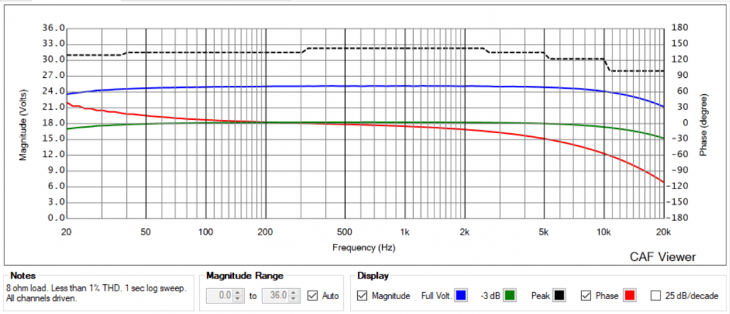
Figure 1 – The Frequency Tab of the CAF report.
The dashed line is a peak tone burst test designed by Don Keele. A wavelet of 1/1-octave bandwidth is applied at each 1/1-octave ISO center frequency. The level is increased until visual deformation of the waveform is observed on an oscilloscope. The peak voltage is recorded. While “peak power” is a misnomer (the peak of the waveform generates very little power), that doesn’t keep it from being used as an amplifier rating. The word on the street is that some amplifiers can put out extraordinary amounts of power for an instant – a statement that is self-contradicting. The objective of the Keele test is to see if the output voltage is higher than the continuous sine wave voltage for the shortest meaningful time increment. If so, the extra voltage swing could be referred to as “dynamic headroom.” For the SRA-4150 (and most amplifiers) it tracks at +3 dB re. the maximum RMS sine wave voltage as it should for a high fidelity amplifier interfaced as a constant voltage source to the load. Some amplifiers get their 2 ohm rating from this signal, resulting in very high power ratings from an amplifier that under this test condition is not producing very much power. I suspect that a 2 ohm load would not change this peak voltage, but the manufacturer (wisely) does not rate the amplifier for 2 ohm operation.
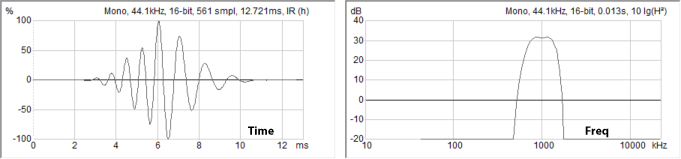
Figure 2 – The Keele tone burst is an asymmetrical wavelet with bandwidth of approximately 1/1-octave. The 1 kHz wavelet is shown. The amplifier is tested at each octave center (31.5 Hz – 16 kHz) and the peak voltage is recorded and plotted on the Frequency plot (dashed line in Figure 1).
The Matrix
The amplifier’s output ratings are found on the Matix tabs. The CAF report has a matrix tab for each output configuration, in this case, “Low-Z” and “Bridged-Mono.” If a switch, wiring mod, jumper, etc. is provided by the manufacturer for configuring the load, that constitutes a “configuration” that gets a unique Matrix tab.
The Total Harmonic Distortion (THD) criteria used in the CAF is 1%. That is a widely recognized and practical benchmark with a long pedigree. While we live in an age of fractional percentage distortion performance, I have yet to see a manufacturer willing to compromise their power rating significantly to realize it. In a competitive marketplace, large power ratings tend to rule.
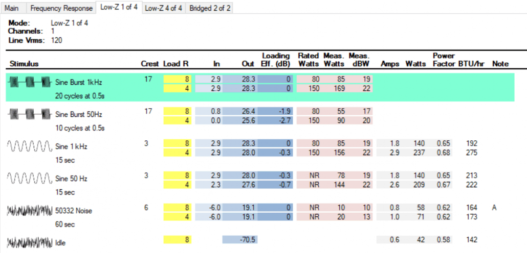
Figure 3- The output matrix for a single amplifier channel
The matrix displays the amplifier’s RMS output voltage for its supported load impedances. The tone burst tests reveal the amplifier’s voltage swing capability. The continuous sine tests reveal its current sourcing ability. The noise test reveals its current draw and heat output under normal (e.g. 1/8-power) conditions. The matrix represents the minimum required test suite needed to reveal the amplifier’s performance and establish its power ratings. It provides a basis to make meaningful comparisons between amplifiers that have the same rated power, as well as to deploy the amplifier for a wide range of applications.
Loading Effect
The Loading Effect column is the simplest way to compare the output voltages for the burst and sine waveforms into the load resistors. An ideal theoretical amplifier would have 0 dB for all burst and sine wave values, meaning that the maximum output voltage was unaffected by signal type or load resistance. The sound system designer can decide if a negative value in this column excludes the amplifier for a specific application.
In this age of multi-channel amplifiers, I usually test both single channel and “all” channels. This can reveal how robust the power supply is under heavy current drain conditions. Few amplifiers can replicate their single-channel performance when all channels are driven by low crest factor signals (e.g. sine waves or heavily compressed program), and very high power amplifiers tend to be limited by the utility power circuit breaker. The SRA-4150 is a moderate-size amplifier and the single channel and all-channel results are within a few dB for most tests.
The Bridged-mono mode swings about twice the voltage as the Low-Z mode. This represents 4 times the low-Z 8-ohm power (about 2 times the low-Z 4-ohm power). As with most amplifiers, the maximum load (minimum ohms value) for bridged mode is 8 ohms due to limits on power supply current.
Conclusion
In this modern world of quiet listening spaces, a fan-less 1RU form factor has a lot of applications. The SRA-4150 should be a solid performer for typical high crest factor program material such as speech and music. It performs less well for continuous sweeps and tones with all channels driven by the same signal. Most amplifiers run out of current under these conditions, and the SRA-4150 is no exception. As always, it is the job of the sound system designer to assess the requirements for the project and work around an amplifier’s limitations. pb
Leave a Reply
Want to join the discussion?Feel free to contribute!