Common Amplifier Format: QSC CXD4.2Q


Images courtesy QSC
I first used the QSC CXD4.2Q during a training seminar in Australia in 2019 along with a Core 110f DSP. It readily handled all of our class demos and even inspired me to add a few more. The Q-SYS platform is especially strong regarding filter implementation and system monitoring. While many performance metrics can be monitored on the amplifier front, Q-SYS Designer™ is highly recommended. Peak and RMS readouts on voltage, current, and power help paint a complete picture of the amplifier’s performance.
QSC discontinued the CXD series of amplifiers in 2019 and replaced it with the CX-Q series. The CXD-series is a textbook example of the decisions and trade-offs regarding combining amplifier channels. The newer CX-Q series is designed to further simplify some of those decisions. I think audio professionals should understand how to do it manually, so I chose the CXD for this article. No matter how “smart” the amplifier is, one must still work within the limits of the utility power circuit to maintain the integrity of the voltage waveform delivered to the load.
Since these articles are tutorial in nature, I’ll use the CXD4.2Q to present some important fundamentals regarding amplifier ratings. Of course, these same principles apply to other amplifiers.
The Common Amplifier Format (CAF) presents a very complete picture of an amplifier’s performance. The freeware CAFViewer™ can be downloaded here. The CAF data file for the CXD4.2Q can be downloaded here. There is a tab for each configuration tested (Figure 1). Tabs with the same color text indicate configurations that were tested simultaneously.
This data is for use in learning and teaching about audio power amplifiers. It is not intended to augment, supplant, or replace the manufacturer’s published specifications. It has not been approved by the manufacturer.

Figure 1 – CAF report tabs. There is no practical limit on the number of tabs in a CAF file.
Multiple Configurations
The CXD4.2Q is a textbook example of how multiple channels can be combined to yield more voltage swing, more current flow, or both. To best understand this, forget about “power ratings” and look at the voltage, current, and load impedance. These provide the most insight into the amplifier’s performance and provide far more information than power ratings (Figure 2).
The 4 channels are designated A, B, C, D. Two channels can be placed in series (A+B) to double the voltage swing. This is commonly called “bridged-mono” or just “bridged.” Two channels can be connected in parallel (AB) to double the available current. This is commonly called “parallel-mono” or just “parallel.” In this article I’ll refer to the configurations as series and parallel. Of course, in either configuration this 4-ch amplifier becomes a 2-ch amplifier, and even a 1-ch amplifier in some configurations. Here’s a link for further reading.
If that makes your head hurt, the same means of power source combining is commonly used with batteries. A single battery type (e.g. AA) forms a building block to achieve higher voltage, current, or both (Figure 3).
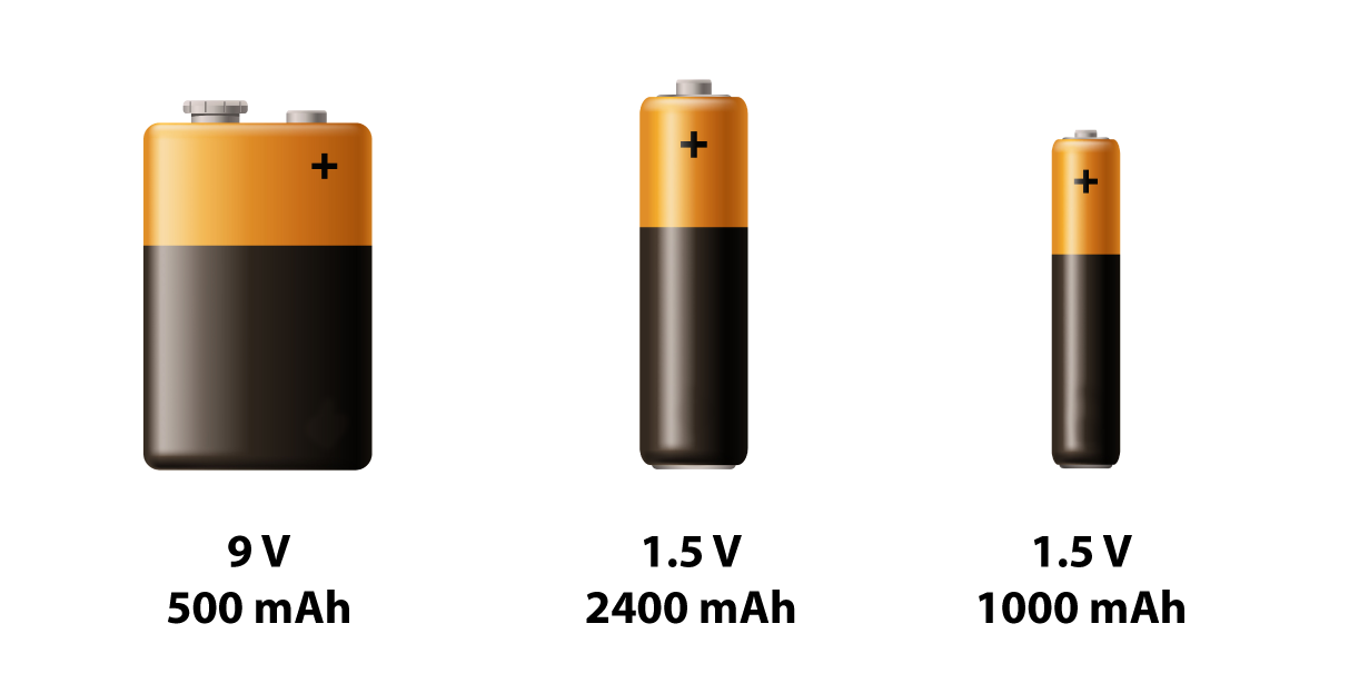
Figure 2 – Batteries are rated in terms of voltage and current, not watts.
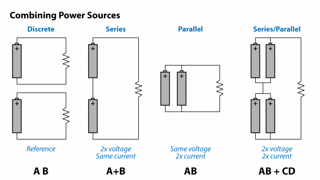
Figure 3 – Combining amplifier channels is in principle like combining batteries to get higher voltage, current, or both.
Caution!
Never assume that a multichannel amplifier can be operated in a series or parallel configuration. Many cannot, and trying to do so may irreparably damage the amplifier. If these modes of operation are supported, the manufacturer will provide the information needed to properly strap the channels.
One-Channel-of-Four
A single channel is the building block and reference for all of the configurations. Let’s examine its capabilities in detail. The “A B C D” tab of the CAF report shows the measured performance of channel “A” while driving all four channels with the same signal and under the same load. The CAF tests the amplifier using a sine burst, 1-sec log sweep, continuous sine wave, and continuous noise. Together, these paint a very complete picture of the amplifier’s capabilities. An examination of the measured performance data reveals that a single channel is optimally loaded at 8 ohms, and can reliably produce about 50 VRMS and just over 6 ARMS into 8-ohms (Figure 4).
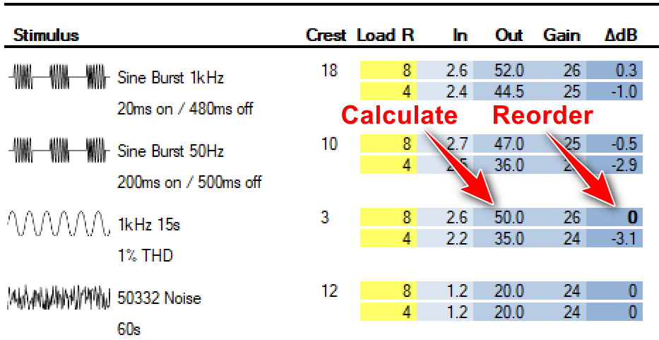
Figure 4 – The 4-ch IO matrix from CAFViewer. Double-click where shown to reorder the matrix using your choice as the reference. Double-click on the output voltage column to launch the Low-Z calculator, pre-loaded with the selected voltage. The ΔdB column shows the change in output voltage caused by different signal types and load resistances. For an ideal voltage source, all values in this column would be zeros.
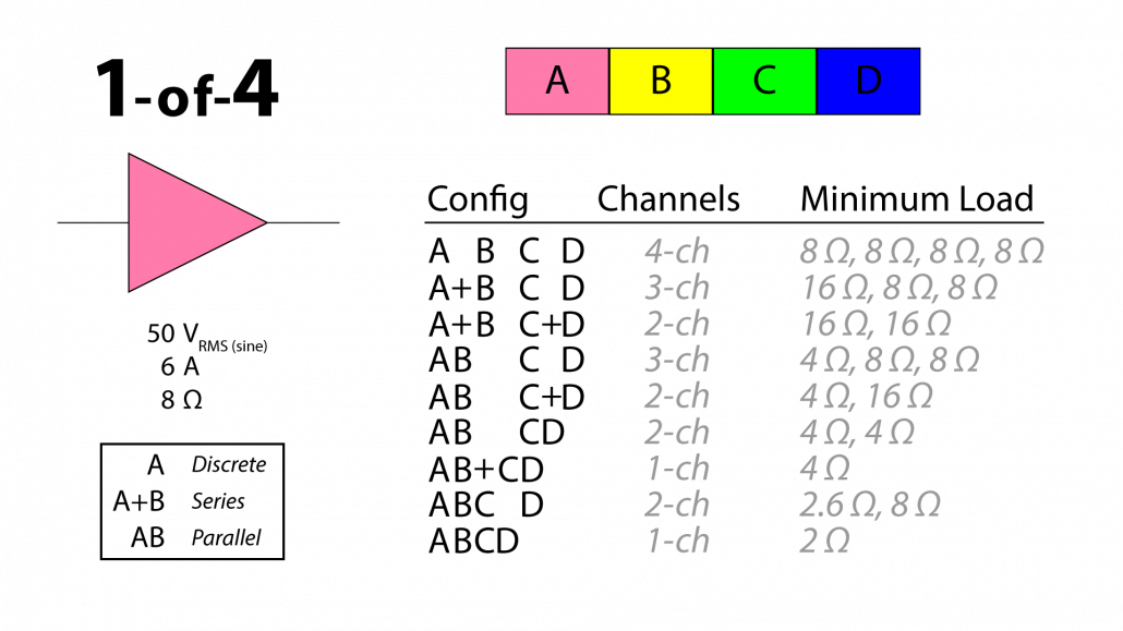 Figure 5 – The (conservative) performance metrics of one-channel, and the ways to combine multiple channels.
I base this on the amplifier’s response to the 1-second log sweep test. This test is a good compromise between the untaxing burst test and the punishing 15-second sine test contained in the IO matrix. In the age of electronic music, one-second is not a long time to expect an amplifier to hold its full power output voltage. The Frequency Response tab in the CAF (Figure 6) shows the amplifier’s output voltage under various loads, starting with one that the amplifier can easily drive (16-ohms) and ending with the lowest load impedance recommended by the manufacturer (2-ohms). There is also a “Z-Sweep” test where the amplifier must drive a reactive (frequency-dependent) load instead of a purely resistive one. If your application needs a linear relationship between the input and output voltage for all signal types in 4-ch mode, 8-ohms is the maximum load (minimum load impedance).
Can it produce 50 VRMS into 2-ohms for any signal type? Yes, but you’ll need to parallel all four channels (the ABCD tab in the CAF file). Sound system design is a game of trade-offs and compromise.
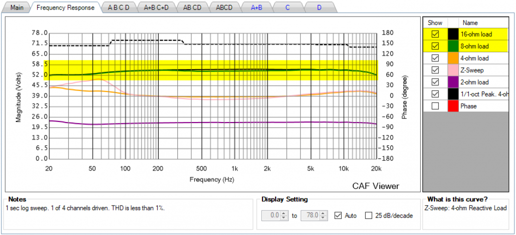
Figure 6 – The CXD4.2Q operates as a constant voltage source down to 8-ohms (1-ch driven). Mousing-over this plot in the CAFViewer will produce a real-time power calculation at 8, 4, and 2-ohms.
Need More Voltage or More Current?
If you need more voltage you can put two channels in series, if more current you can put two (or more) channels in parallel. If you need more voltage and current, you can put all four channels in series/parallel. Let’s break it down.
A 4-ohm load requires 2x the current as an 8-ohm load. This will require 2 channels in parallel (AB or CD).
A 2.6-ohm load requires 3x the current as an 8-ohm load. This will require 3 channels in parallel (ABC).
A 2-ohm load requires 4x the current as an 8-ohm load. This will require 4 channels in parallel (ABCD).
A 70.7 V line requires about 25 VRMS and 100 Vpeak. Two channels in series can easily provide that and will be fully loaded at 8-ohms (A+B or C+D).
A 100 V line requires slightly more (about 35 Vrms and 140 Vpeak). Two channels in series can easily provide that into 16-ohms. You can think of the A+B mode as a 100 V amplifier that can be backed off a bit to drive a 70 V line at rated voltage.
Figure 5 summarizes the ways of combining the channels.
Deployment Philosophy
A “conservative” approach to amplifier deployment is to assume that the amplifier will encounter a worst-case scenario. This would be a sinusoidal signal of several seconds duration at full output (clipping or limiting) into the lowest impedance for which the amplifier can hold its output voltage. Design for that and you probably have everything else covered. This will allow the amplifier to operate with some headroom regarding current production for less intense program.
It is possible (and maybe likely) that the amplifier may never be called upon to produce its full-scale voltage into its minimum rated impedance. If that is the case, you may get away with increasing the load on the amplifier (reducing the load impedance) beyond the guidelines given here. This less conservative design philosophy is common and works for many applications. It’s up to the sound system designer to determine how hard the amplifier will likely have to work once it is deployed. We have all experienced scenarios when a sound system “ran out of gas” during an event because the system was pushed harder or longer than usual. A conservative design philosophy anticipates this situation.

Figure 7 – A conservative design approach plans for the worst-case scenario.
In Q-Sys Designer an amplifier output must be connected to a loudspeaker object in the GUI. This can be a QSC-branded loudspeaker or a “generic” model (Figure 8). These loudspeaker objects incorporate RMS limiting for thermal protection and peak limiting for over-excursion protection. In the generic object the voltage limits for both peak and RMS can be selected by the user. The CAFViewer’s calculators will help you determine these voltages from a loudspeaker’s power rating.
Current Limits
A single CXD4.2Q will fully load a 20 A utility power circuit. In some of the tests in the CAF it pulled more than 20 A. This must be kept in mind when deploying the amplifier. I could not find a suggested circuit breaker size in the QSC support literature, but one can make a case for 20 A (120 V) if one wishes to take the amplifier to its limits regarding power generation. That’s a LOT of current and it imposes a practical limit on how much audio power the amplifier can produce.
Driving the Amplifier
The CXD4.2Q is optimized for use within the Q-SYS ecosystem. The drive signals to each channel are delivered via the data network via a category cable, and a gain control is provided to trim each channel to the desired level. While this is the best way to feed the amplifier for most applications, I drove one of the analog Euroblock inputs for testing, routed to the amplifier input using Q-SYS Designer software (Figure 8).
For testing, a “generic” loudspeaker type was assigned to each output channel and the RMS and peak limiting functions were set high enough to not engage. The desired input sensitivity is selected in the GUI and ranges from about 27 dBu (lowest sensitivity) down to 0 dBu (highest sensitivity), with a gain of about 9 dB to 36 dB respectively. This broad range allows the amplifier to be driven to full output from just about any source, and it can handle full line-level signals (+4 dBu plus 20 dB peaks) from professional sources. This is notable and serves as a reminder that QSC has been in the amplifier business for a long time. They fully understand the range of input levels that a modern amplifier may be exposed to.

Figure 8 – A “generic” loudspeaker type was used, with limiter settings set at their extremes (blue box).
New in the CAF: Tab Groups
The tabs with blue text in the CAF file were measured simultaneously (Figure 1). This is necessary when the channels are operated under multiple configurations, such as two channels in series and the remaining two channels either parallel-ed or operated independently. While there are many possible combinations, and no practical limit to the number of tabs in a CAF file, I picked one such configuration to include in the CAF report.
Amplifier Monitoring
Q-SYS Designer reports multiple performance metrics in real-time. This is extremely well-done, useful, and important for managing multiple amplifiers that may be distributed throughout a large venue. The load impedance can be measured by the amplifier in the A B C D mode of operation, using a 22 kHz tone, 20 Hz tone, or the actual program material. Hopefully, this will eventually be extended to all operational modes, and maybe it already is in the new CX-Q series. The reported headroom in the GUI is based on the output voltage, as it should be. It functions with no load connected to the amplifier, and therefore with no current flowing. As goes the voltage, so goes the SPL from the loudspeaker.
Metering Power
Be careful with the GUI’s power readout. If you drive your loudspeaker until the power shown matches your loudspeaker’s power rating, you’ll likely damage your loudspeaker. This is not the fault of the amplifier or how it monitors power. It is because loudspeaker power ratings are calculated based on the maximum voltage that the loudspeaker can handle, not the power. The loudspeaker’s rated power is calculated from this voltage using its rated impedance. Since the loudspeaker’s average impedance can be significantly higher than its rated impedance, a loudspeaker drawing 100 W (by calculation) is likely drawing less than that for broadband program material. If you feed it 100 W as indicated by the power meter the applied RMS voltage can be higher than the voltage used to rate the loudspeaker, resulting in smoke. Seem confusing? The solution is to determine your loudspeaker’s maximum voltage by calculation, and then watch the voltage readout in the GUI to stay below that (Figure 9). Better yet, set the RMS limiter in the loudspeaker object at or below the loudspeaker’s maximum RMS voltage (Figure 8).
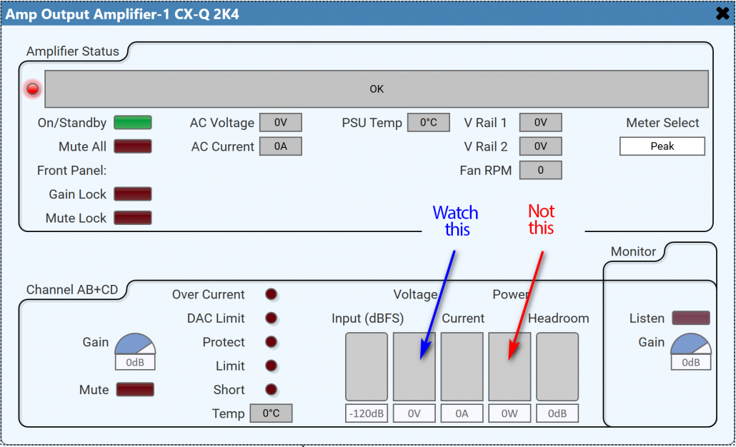
Figure 9 – Be sure to watch the voltage meter (blue arrow) not the power meter (red arrow) to stay within your loudspeaker’s limits.
Conclusion
Class D amplifiers continue to amaze regarding efficiency and voltage swing. They are usually current-limited by design, the utility power circuit, or both. This is especially true of large, multi-channel amplifiers. The CXD4.2Q is a textbook example of how multiple amplifiers can be combined to get more voltage, more current, or both by distributing the load between multiple channels. The CXD’s successor, the CX-Q series will allow the total amplifier current to be allocated dynamically on demand. That’s a useful feature, but it doesn’t obsolesce any of the principles presented in this article.
As all of the things around us get “smarter,” so do audio power amplifiers. This can allow better integration with the loudspeaker, allowing the two to form a system that includes sophisticated signal processing, peak and RMS protection, and performance monitoring. The result is maximum fidelity, SPL, and increased reliability. pb
