Common Amplifier Format: Lab Gruppen E 12:2
Disclaimer: This third-party testing was performed on a unit purchased from the normal distribution channels. It is not intended to supplant, replace, or challenge the manufacturer’s published data. Anyone deploying this amplifier should consult the manufacturer’s literature and follow the instructions contained therein.

Operational Modes
Table 1 presents the rated amplifier output power as per the specification sheet, along with the calculated voltages for each load resistance. Apparent from the table is that the amplifier is expected to operate as a voltage-optimized source down to 4 ohms in the Low-Z mode (8 ohms in the 70 V mode). Below that the voltage will limit to protect the amplifier. Note that since the amplifier can be loaded to 8 ohms in the 70 V mode, that would be the preferred mode for driving an 8 ohm loudspeaker due to the higher output voltage. This is clearly stated on the manufacturer’s spec sheet.
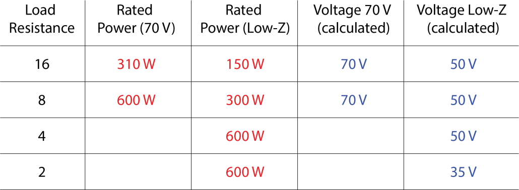
Table 1 – Expected output voltages as calculated from the rated power.
The CAF report includes an I/O Matrix tab for each mode of operation. The manufacturer specifies that both channels were driven for all power tests, so that is how I initially tested it.
Current Sharing
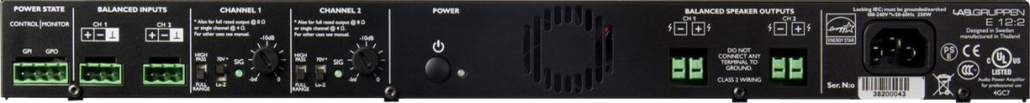
Balanced Loudspeaker Outputs
These days those practices could be “amp killers” and should be avoided, at least in sound reinforcement systems. NEVER ground one side of a loudspeaker line (unless it’s in a Ford F150).
Burst vs. Continuous Testing
The E 12:2 was not designed to hold a sine wave at the rated power, so if your application requires that, keep looking. It will quickly throttle back to a lower voltage as per the limiter circuitry. I’m not suggesting that this is good or bad, it just “is.” The sound system designer should know about this behavior and consider it when selecting the amplifier for a project. Those that pick the smallest, lightest weight “600 W” amplifier could be in for a surprise.
The CAF I/O Matrix allows the rated power to be specified per the load impedance and signal type. I am an advocate for specifying a sine wave rating at a lower power, such as -3 dB from the burst test rating, if the amplifier cannot reproduce a sine wave at the rated power.
The Frequency Response Tab
The dashed line shows the peak output voltage of a wavelet driving the amplifier to visual deformation of the waveform on an oscilloscope. This demonstrates the very high instantaneous output voltage of the amplifier.
The blue plot shows a 1-second log sweep at the rated sensitivity of +4 dBu. The output voltage throttles back almost immediately. I had to drop the drive signal by 10 dB for the amplifier to maintain the same output voltage for the full duration of the sweep (green plot). See my article Driving the 4-ohm Load for the implications.
That said, the matrix reveals that this is a quite different “600 W” amplifier than other offerings in the marketplace.
Alternative Rating Methods
The term “rated” means that the manufacturer is free to choose the power rating of the amplifier based on the measured power. In the case of the E 12:2 the highest short-term output voltage was used to determine the power rating. Figure 1 shows the I/O Matrix for 1 channel of operation. The delta dB column shows what the output voltage does under various load conditions, using the highest output voltage as the reference.
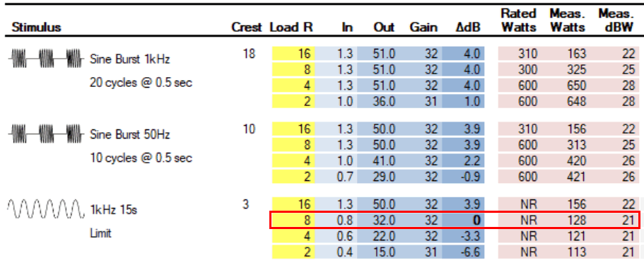
In CAFViewer, any value in the delta dB column can be used for the reference. Just double-click the desired value. Figure 2 shows the matrix using the continuous sine wave 8-ohm value as the reference.
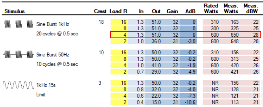
Figure 1 – I/O Matrix arranged using Sine Burst @ 4 Ω for the rated power.
Given the above two scenarios, is this a 600 W amplifier that limits on a sine wave, or is it a 125 W amplifier with 4 dB of “dynamic headroom?” One could make a case for either. I guess it depends on whether one is selling it or using it. It also depends on the intended program material. I remember an era where we did not have to consider that when choosing an amplifier.
Yes, there are some philosophical aspects to amplifier ratings. The I/O Matrix of the CAF lets the user decide how to rate the amplifier.
Conclusions
The E 12:2 is marketed as a “1200 watt” amplifier. With regard to the “heating power” of the amplifier (the best measure of output power when driving a resistive load), it’s no where near that. It’s more realistic to think of it as a 50 V or 70 V amplifier designed for use with high crest factor signals. The limiting circuitry prevents an overload condition that could damage the amplifier. The matrix makes it clear that it is still better to not load the amplifier below 8 ohms if one requires high fidelity for low crest factor signals, especially at low frequencies with both channels driven. This is not a subwoofer amplifier.
These performance limitations are offset by the amplifier’s 1 RU chassis, light weight, and low noise operation (even with the fan running at high speed). The distortion was well below the 1% THD allowed by the CAF under all tested scenarios.
As always, sound system designers should consider all aspects of an amplifier’s performance when choosing one for a specific application. pb
Leave a Reply
Want to join the discussion?Feel free to contribute!