Amplifier power ratings are good for window shopping and water cooler chats. If you need to drive a real-world 4 ohm Load, you need the matrix.
Long ago, 8 ohms was established as a practical impedance for a loudspeaker. If made higher, it gets more difficult for the amplifier to force current through the loudspeaker’s voice coil to make it move. If made lower, the amplifier may run out of current, since the load impedance is the primary limiting factor for current flow. While many other impedances are possible, 8 ohms is a historically-supported value used by loudspeaker and amplifier designers. It also happens to be the resistance that will draw approximately 15 amps of current from a 120 Vrms household electrical circuit, so it represents the minimum numerical load value (maximum load) that 120 V 15 A utility power circuit can drive. Most amplifiers have no problem driving 8 ohm loads, but in special applications that use lower impedances, a closer look is needed.
The General Concept
A real-world 8 ohm loudspeaker has a frequency-dependent impedance, meaning that it can be higher or lower than 8 ohms at any given frequency. It can exceed 8 ohms by any amount, but by Standard it cannot drop below 8 ohms by more than about 20%, meaning that an 8 ohm loudspeaker can be as low as 6-ish ohms over its usable bandwidth. For that reason, as a safety margin audio power amplifiers are usually designed to drive loads lower than 8 ohms, with 4 ohms being a common design objective. In other words, 4 ohm capability is needed to drive a real-world 8 ohm load. Two “8’s” in parallel could be as low as 3 ohms at some frequencies.
A major decision for the amplifier designer is available current, both in amount and duration, and higher current means higher price. This financial reality provides a motive for limiting the value.
A Specific Application
While the above describes the general case amplifier-to-loudspeaker interface, there may be a need to get more into more detail for a specific application. In my case it was the need to drive 4 loads with the same signal from a single amplifier, with each load having a rated impedance of 4 ohms. The application is acoustic testing, and the objective is to produce as much sound energy as possible from an omnidirectional source into a cavernous space. The program material may be speech or music, but the system needs to be designed around a 14-second sine wave sweep (20 Hz to 20 kHz +/- 1 dB) used to capture the room’s impulse response. I’ll design for the sine wave, and then consider the system’s performance for other program material.

Photo 1 – Caverness spaces need a lot of sound power for acoustic testing. The sound power level (LW) is an important specification for acoustical test loudspeakers. Shown is Hinkle Fieldhouse in Indianapolis, IN. Testing in this space is what motivated me to look for a better way to drive the the test loudspeaker. The “200 watt-per-channel” amplifier I was using could not drive the load(s) while maintaining the integrity of the sine sweep.
The loudspeaker is an Outline GlobeSourceTM (GS) radiator – a premium “dodecahedron-like” loudspeaker. The published rated power handling is 1600 W continuous, a rather nondescript rating since the 12 transducers are divided into 4 channels. There are 4 circuits of 3 loudspeakers each, so the one-number power rating presumably translates to 400 W per circuit, each rated at 4 ohms. Plugging these values into the power equation suggests that that each circuit can handle 40 Vrms, and since the objective is to produce as much sound power as possible I need to consider driving it to near that value.
Also, at face value it appears that a 4-channel amplifier rated at 400 W/ch into 4 ohms will fully power the GS. That translates into 40 VRMS for a sine wave signal. I have concerns about hitting the GS with a continuous signal of that magnitude without some further investigation. It’s an expensive device and the replacement parts come from Italy.
It is of the utmost importance that the voltage of the sine wave not change over the course of the 14-second sweep. If the amplifier voltage sags under load then the non-linearity will negate the validity of the recorded sweep for post-processing via deconvolution into the room impulse response. This concern suggests the need to dig deeper into the specifications of the GS and the prospective amplifier.
Getting the Details
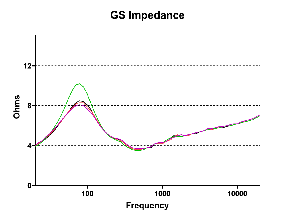
Given the expense of the GS and the need to run it to its limits, I did my own testing regarding its impedance and power handling. “Rated” values have their place, but they tend to be vague and can obfuscate the physical reality. The measured impedance of one circuit (of four) is shown in Figure 1. Note that as described in my opening paragraph, the minimum impedance does indeed drop below the rated impedance of 4 ohms. Again, there is nothing wrong here, as this is allowed by IEC Standard (by up to 20%). But, it does make it tougher on the amplifier, since the lower impedance means higher current draw, especially when the program material is a sine wave.
Figure 1 – The magnitude of the load impedance for each GS circuit. Why are they different? That requires a different investigation.
I used my “
Toaster Test” to determine the onset of power compression, and determined that the maximum continuous voltage (E
MAX) that one circuit can handle is 22 V
RMS. There is no doubt that it can handle more for a short burst waveform, but my intent is to use a sine wave and I have to design for that. That’s nearly 6 dB below the 40 V
RMS suggested by the power rating, so my closer look probably kept me from smoking the GS.
From these tests I now know that I need four amplifier channels that can simultaneously produce 22 VRMS into 4 ohms for at least 14 seconds with stable amplitude over that span. My space budget (it’s a portable system) is 2 rack units (RU). The power equation suggests a minimum amplifier power rating of 121 watts into 4 ohms will do the job.
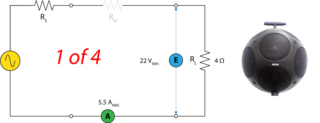
Figure 2 – The room testing loudspeaker consists of 12 transducers spread over 4 circuits. Each has a rated impedance of 4 ohms. Driving it with 22 VRMS mandates 5.5 ARMS of current from the amplifier. That’s 121 W continuous, since W = EI.
Amplifier Ratings
Three major variables that must be addressed by amplifier designers are
- Output Voltage
- Output Current
- Output Current Duration
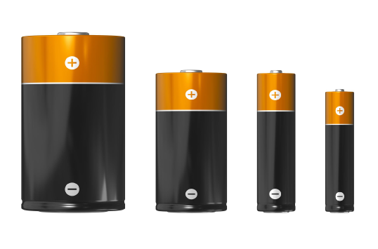
This is not unlike the rating system used for batteries. Note that without Item 3 – Output Current Duration, “1.5 V” batteries of different sizes could appear to be the same, since they only differ in current production/duration (Fig. 3)! Since power is the “rate of doing work” time matters, and a real world power rating is influenced by all three variables. Unfortunately the importance of Item 3 is rarely considered by end users and can be completely masked by a “power rating” that just considers Item 1 and Item 2 for a small span of time. This can make amplifiers that are very different appear to be similar.
Figure 3 – All of these batteries can produce 1.5 VDC. The difference is into “what load” and “for how long?” This is why they are rated in mAH (milliamp-hours). Somehow audio power amplifiers have evaded this detail.
Many modern amplifiers cannot hold their output voltage over time when driving a 4 ohm load with a sine wave. One that can will have a 4 ohm sine wave power rating that is 2x the 8 ohm rating – a rarity, and admittedly not always a necessity. In fact, it may be impossible to select an amplifier for my special application using typical power ratings, since they cook the voltage, current, time, and load resistance into one number, masking some important specifics about the amplifier’s performance.
The Contenders
I have 3 amplifiers in my inventory that “fit the bill” based on their rated power, at least at face value. I’ll call them Amp 1, Amp 2, and Amp 3. Here’s a short description of each.
Amp 1 is a 4-channel 1 RU convection-cooled unit. It is rated at 80 watts/ch into 8 ohms, and 150 watts/ch into 4 ohms, with all channels driven. At face value this appears to exceed the 121 W needed to drive the GS.
Amp 2 is a 2-channel 1RU convention-cooled unit rated at 200 watts/ch with both channels driven. My application will require 2 units, but that still fits my 2 RU size limit. The rated power is the same for 16, 8, and 4 ohms. This suggests that the output voltage is load-dependent – the result of an “only the power matters” design philosophy. Given the shape of GS impedance curve, this behavior may be a deal-breaker for driving it with a 14 second sine sweep.
Amp 3 is a “multi-mode” amplifier with 8 channels that can be used independently or combined in various configurations. The mode that looks most promising for my application is the use of 2 channels to form a single amplifier with increased current output. That would give me 4 channels with solid 4 ohm performance, packed into 2 RU. But, I need to know whether the 4 channels can be driven simultaneously with a sine wave to 22 VRMS when loaded to 4 ohms when fed by a single 15 amp utility power circuit. Multi-channel amplifiers can run out of current when the channels are used simultaneously, especially for low crest factor waveforms like sine waves, square waves, and compressed program material.
Apples vs. Oranges?
To compare the amplifiers I produced a Common Amplifier Format (CAF) specification set for each. The CAF includes a matrix that shows the amplifier’s output voltage for 3 different signal types into its rated load resistances. There is a burst test, a continuous sine test, and a continuous noise test. Most importantly, it clearly shows how the amplifier’s output voltage (in decibels) changes under load using a measure I call the “Loading Effect.” I need a Loading Effect near zero for my application, which means that the amplifier basically works like an ideal voltage source where the voltage stays solid as the current flow tracks the load impedance as it changes with frequency. It shows how the voltage holds up for different types of waveforms.
The CAF Matrix effectively reveals information about the 3 amplifier characteristics described above, but presented through the lens of output voltage vs. resistance. Since the applied voltage the only way to throttle the current into a fixed load, its behavior indirectly reveals the current capabilities of the amplifier.
Let’s evaluate the Matrix for each amplifier.
Amp 1
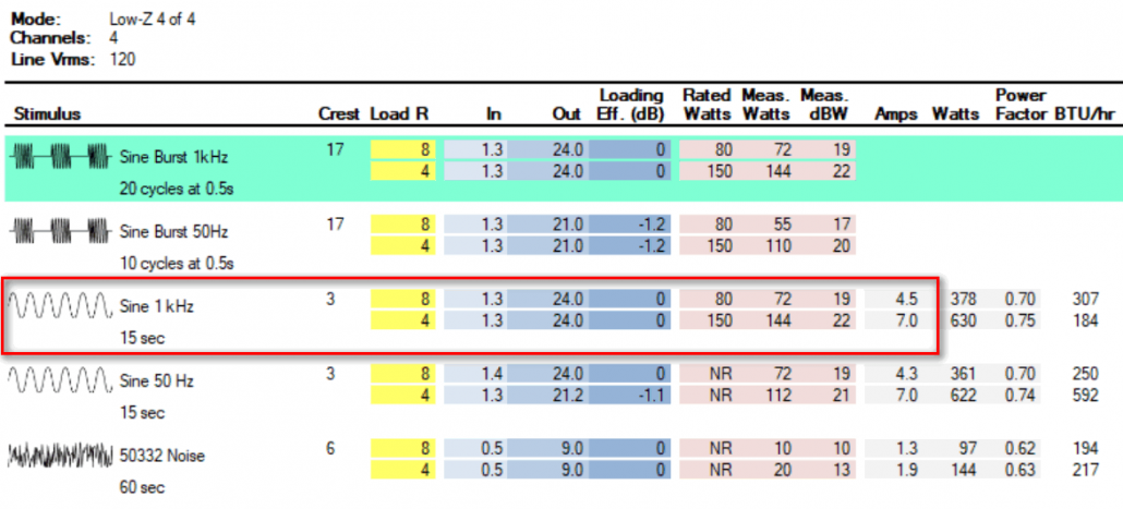
Figure 4 shows the matrix for Amp 1. I have highlighted the sine wave performance. Note that it can produce 24 VRMS for 15 sec into 4 ohms. This amplifier meets the design criteria, and it is only 1 RU and convection cooled. Nice. It’s definitely a contender.
Figure 4 – Amp 1 I/O matrix. It can hold 24 VRMS into 4 ohms for 15 seconds, when driven by 1.3 VRMS.
Amp 2
Figure 5 shows the matrix for Amp 2. Note that its power rating (200 W) is higher than Amp 1, so at face value it should work. The matrix reveals that while the maximum VRMS for a burst sine is 29 VRMS, it drops to 18 VRMS for a continuous sine. This is well below the 22 VRMS needed to drive the GS to its full acoustic output. The Loading Effect column shows that the amplifier voltage fluctuates wildly under load. This can result in an uneven frequency response, since the load impedance varies with frequency. It’s a 200 W rated amplifier that cannot deliver 121 W for this application. See the problem?
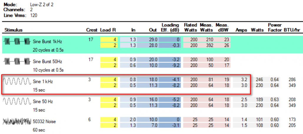
Figure 5 – Amp 2 I/O matrix. It can hold 18 VRMS into 4 ohms for 15 seconds, when driven by 0.8 VRMS.
Amp 3
Figure 6 shows the matrix for Amp 3. It can deliver 36 VRMS into 4 ohms for the continuous sine. It will be coasting at 22 VRMS. Note that even though it is rated for 2 ohm operation, the VRMS drops significantly due to the 15 amp limit of the utility power supply. This is to be expected and is mandated by the laws of physics. Utility circuit current is always a consideration with large, multi-channel amplifiers, but one that is obfuscated by typical power ratings which are often based on burst testing alone (the green-shaded area in the matrix).
Note that for the sine burst signal the maximum output is 50 VRMS. That’s about +6 dB higher than Amp 1. While I wouldn’t dare drive the GS with a sine wave at this level, it will provide more peak room for music and speech signals. That’s significant for my application.
The Noise section of the matrix is the quickest way to get to the amplifier’s performance for typical speech and music program. It can produce 19 VRMS into 4 ohms with 12 dB of peak room, all channels driven with about 6 amps of current draw. This will drive the GS to near its thermal limit and make a lot of sound in the space, with only one utility power circuit required.
The amplifier is 2 RU and is fan cooled. The fan cooling is a down side, as I will sometimes use the rig in very quiet spaces for sound isolation testing. But, at least the fan is throttled based on use, and if I’m producing high SPLs the noise may not be an issue. Amp 3 is by far the largest and heaviest of the 3 amplifiers under consideration.
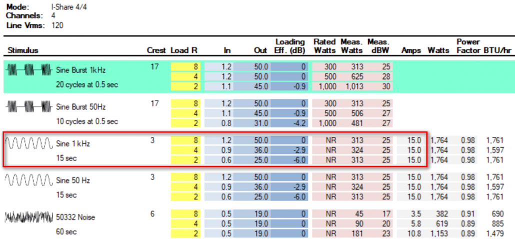
Figure 6 – Amp 3 I/O matrix. It can hold 36 VRMS into 4 ohms for 15 seconds, when driven by 0.9 VRMS. This is 4.2 dB higher than needed, so reducing the input level by that amount will yield 22 VRMS to the load.
The Decision
The Matrix shows that Amp 1 will suffice for reproducing the 14 second log sine sweep needed for room acoustics testing. Amp 3 will also work, with additional peak room for playback of noise, music or speech waveforms. Amp 2 won’t cut it for my specific application, but should work satisfactorily for more general uses, such as high crest factor speech and music. Amplifier power ratings rarely provide enough information for users to make such decisions, which was one of the driving motivations for the CAF.
I decided on Amp 3 since it will allow higher playback level of noise, music, and speech than Amp 1. It will allow me to drive the GS to its maximum possible acoustic output. As a bonus, this amplifier has a GUI that monitors the output voltage of each channel. This will allow me to creep right up on the maximum allowable voltage for the log sweep without danger to the GS. Of course that requires a PC on site. Even without the GUI the drive signal that produces 22 VRMS can easily be determined from the Matrix by displaying the voltages in dBV and subtracting 4 dB from the input signal to the amplifier. This takes it from -1.2 dBV to about -5 dBV. My NTI MRPro, used to produce the log sweep, indicates the signal level so as long as I keep it under -5 dBV the GS should not be in thermal danger.
Decision made, I set out to package it into a transportable form factor, along with a powered subwoofer (Photo 2).
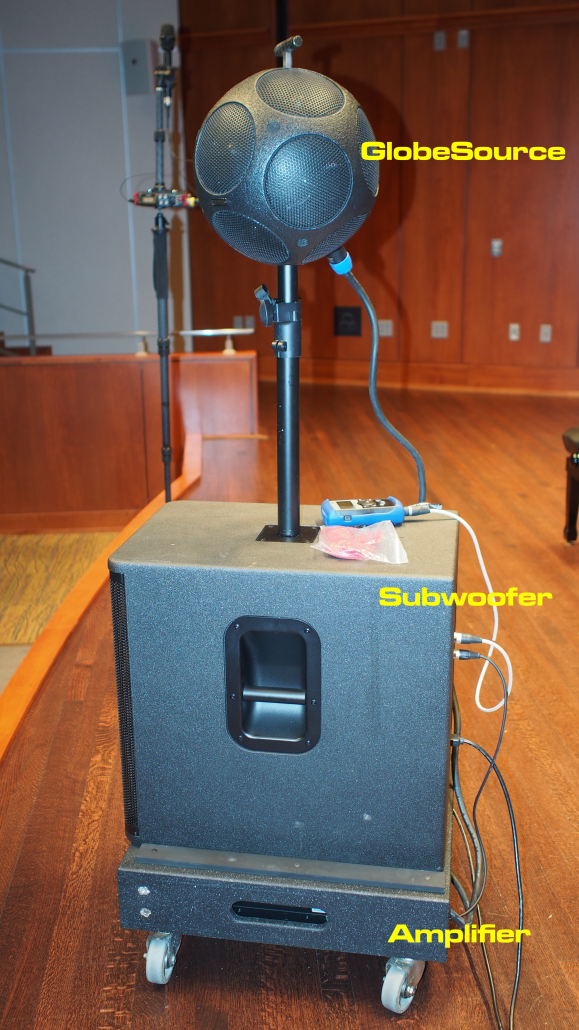
Photo 2 – The GlobeSource, subwoofer, generator, and amplifier rig. It travels well, rolls well, and produces a LOT of sound.
To Summarize
That’s a lot of numbers and a lot to think about. Let’s review:
- The objective is to get the highest possible SPL from a specific loudspeaker.
- Its obscure power and impedance ratings prompted me to measure them for myself.
- This reveal the required amplifier characteristics to drive the load.
- Amplifier ratings don’t usually provide sufficient detail to know the amplifier’s performance under heavy load with sine wave.
- A CAF report does, and producing one gave me the exact information needed.
- I now have every reason to believe that my test rig can achieve the maximum possible SPL from the loudspeaker without damaging it in the process. The result is the best possible signal-to-noise ratio for acoustic testing in large spaces.
Conclusion
Amplifier power ratings are good for window shopping and water cooler chats. Breaking them down into signal type, voltage, and resistance yields vastly more information, allowing more accurate amplifier selection and meaningful comparisons between makes and models. One should not have to buy an amplifier and try it to determine if it is adequate for a specific application. That takes time and costs money.
Our industry’s fixation on power ratings no doubt comes from the utility company (as does the 8 ohm load). There are indeed similarities between utility power and audio power distribution methods. But, Duke Energy works with a fixed voltage and frequency, allowing power ratings to yield a more complete picture of circuit loading. Audio amplifier voltages vary wildly with time and have broadband spectral content. Preservation of the waveform shape matters a LOT, so power ratings alone don’t cut it. We also need to work with levels in dB in lieu of volts. CAFViewer allows the user to select volts, dBV, or dBu – whatever unit system is most meaningful to the system designer. For those wishing to further investigate the CAFViewer and the amplifiers described in this article, I have produced a special CAF file for download.
Amplifier Comparison CAF File
When you really need to know what an amplifier can do, you need the matrix. pb



Leave a Reply
Want to join the discussion?Feel free to contribute!